Design Guidelines: Overmolding & Insert Molding
Our basic guidelines for overmolding and insert molding include important design considerations to help improve part manufacturability, enhance cosmetic appearance, and reduce overall production time.
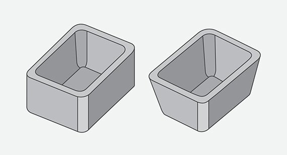
Size

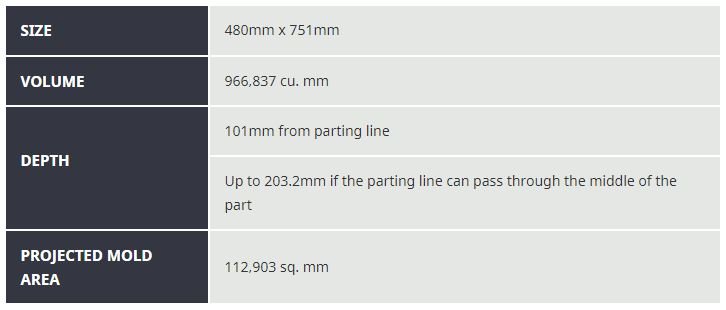
Height may be limited if using a silicone as the overmold material, and deeper parts are limited to a smaller outline. Minimum part volume is 0.025 cu. in. (40.98 cu. mm). With substrate molds, we can maintain a machining tolerance of ±0.003 in. (0.08mm) with an included resin tolerance that can be greater but no less than 0.002 in./in. (0.002mm/mm). With thermoplastic overmolds, tolerances remain the same as substrate molds, however, if the overmold is LSR, then tolerances shift to 0.025 in./in. (0.025mm).
Insert Molding Capabilities
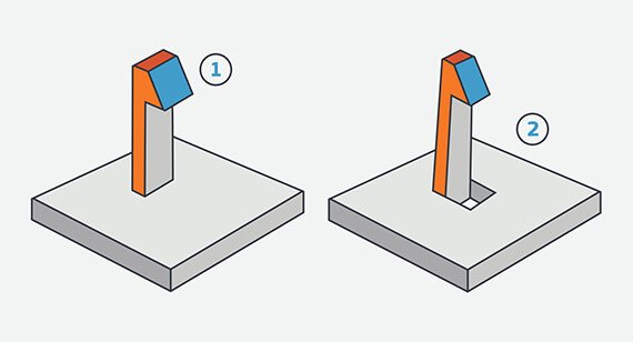
Instead of a mold that produces a final part using two separate shots like overmolding, insert molding generally consists of a preformed part—often metal—that is loaded into a mold, where it is then overmolded with plastic to create a part with improved functional or mechanical properties. We currently accept inserts from PEM, Dodge, Tri-Star, Spirol, and Tappex.
One way insert molding is used is with threaded inserts, which reinforce the mechanical properties of plastic parts’ ability to be fastened together, especially over repeated assembly. Bushings and sleeves are another great way to increase part durability for mating components that need more abrasion resistance due to moving parts.
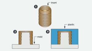
A threaded insert is placed atop a mold core where plastic is molded over it to form the final component.

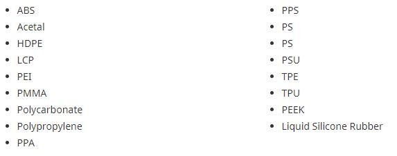
Materials:

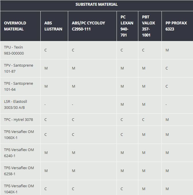
Overmolding Material Bonding
Chemical bonding between overmolded materials is possible, but material compatibility should be considered in order to achieve desired bond strength. Incorporation of an adequate mechanical bond is strongly recommended if bonding is critical to your application. An undercut is a good example of a mechanical bond.

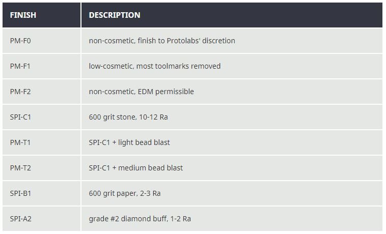
Surface Finishes:
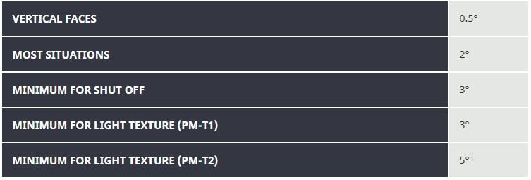
Draft:
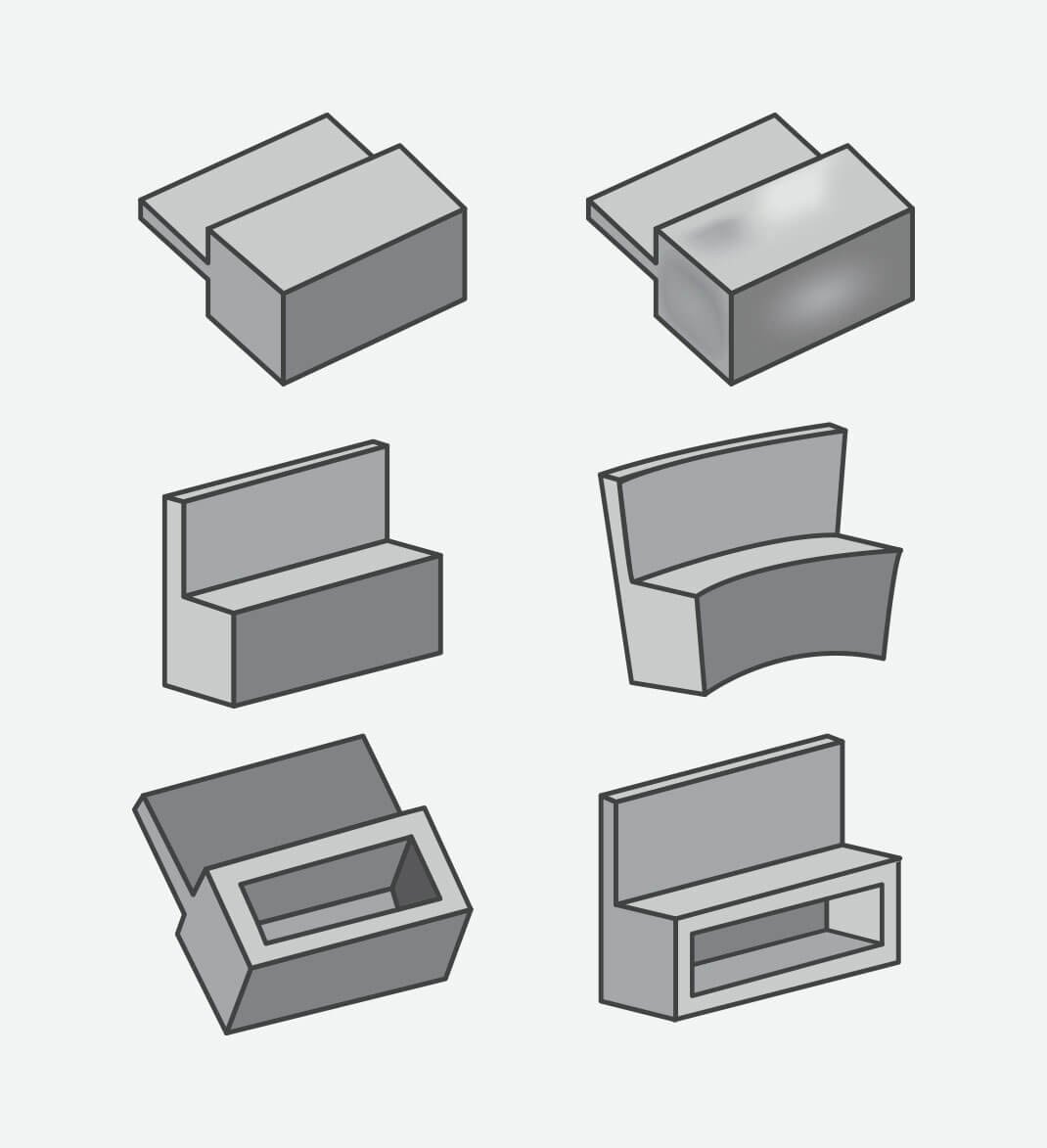
Undercuts
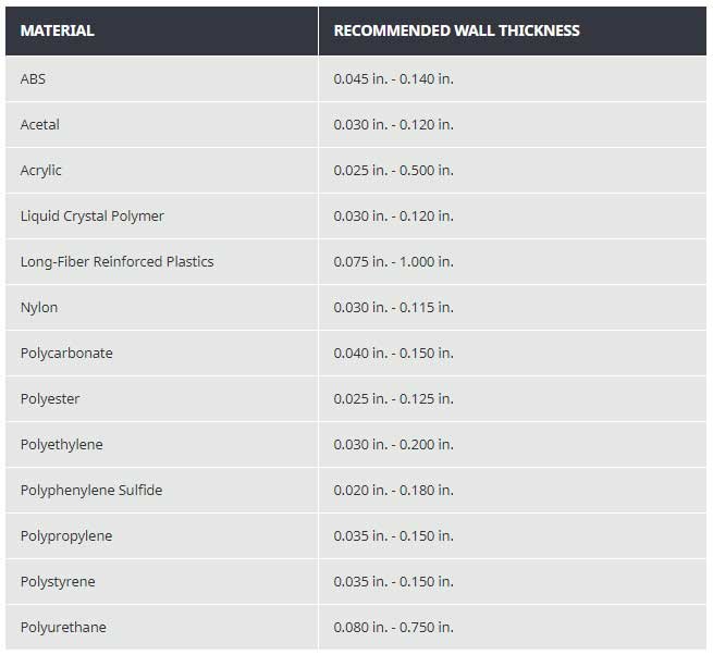
Wall Thickness
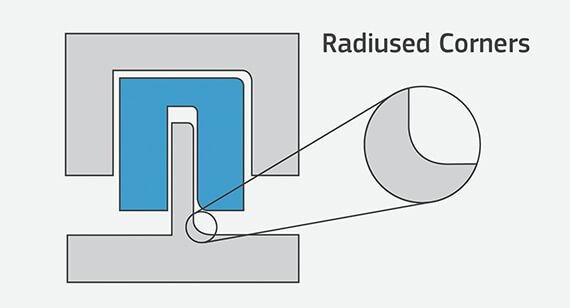
Radii
Some part corners will have a radius rather than a sharp edge since we use an automated CNC milling process to make the mold for your parts. This typically does not require a change to your model, but resulting radii are identified before the mold is milled.
Free moldability analysis within hours
Request More Information
Thanks for your interest in Protolabs. Please let us know how we can provide more information on our services. Once we receive your comments, an applications engineer from our team will follow-up as soon as possible.
If you have a 3D CAD model of your part ready, upload it online now to receive an interactive quote with free design for manufacturability feedback within hours.